This guide is intended as general information only. If you are uncertain of your rights or interests, please seek professional legal advice. Landgate staff are not able to give legal advice or to draft your documents. Please read our Terms of Use above.
1. Digital Data (replaces SPPM Chapter 16.1)
Digital Data is an electronic record of a survey.
Regulation 3 of the Transfer of Land (Surveys) Regulation 1995 requires that Digital Data must accompany every survey plan and survey-strata plan lodged in Landgate.
The data must be supplied in the format specified by the Inspector of Plans and Surveys.
Such digital information is to be regarded as being part of the Plan for the purpose of certification by the surveyor under the general regulations.
Cadastral Survey Data (CSD) file format version 2.0 is the specified standard for format of digital data. Refer to the Cadastral Survey Data (CSD) User Guide (APX-05) to assist in the compiling of (CSD) files.
2. CSD File Requirements (replaces SPPM Chapter 16.2)
2.1. Polygons on Plan
All polygons on the Plan including Surrounds, Easements and portion only Covenants and Notifications burdening and benefiting land within the Plan are to be included in the file (A surround polygon is required for a one lot plan). If the subject of the survey is split into 3 sections then 3 surround polygons are required.
2.2. Roads
To ensure roads are depicted correctly in Landgate’s spatial systems, road polygons must be created in CSD files to the full extent of each road name (including truncations) that appears on the Plan.
Roads are to be captured in segments in the digital file; as determined by the connections across the roads shown on the plan. Each segment must have the correct road name and be fully dimensioned with angles and distances.
Road names must not be abbreviated (e.g. Use ‘John Street’ not ‘John St’). This also applies to the road names in the street addresses attached to lots in the CSD files.
2.3. Distances and Angles
All the distances and angles on Plans, including those that define interests (e.g. easements) or subject to Executive/Survey Registration Minutes, are to be shown as ‘measured’ and to be given attributes of ‘surveyed measured’ for distances and ‘measured’ for angles in the CSD file; even if the field record shows them as calculated from offsets or radiations. That is, the ‘measured’ attribute is to be used for all boundary dimensions on a plan regardless of whether it is directly measured, derived from eccentric measurements or calculated from missing element solutions eg lost corner restoration.
The above also applies to eFB_CSD files complementing SSA Survey Sheets.
2.4. Lot Areas
Lot areas in CSD file to be same as Plan and field record.
2.5. Changes after lodgement
All requested changes to plans of surveys after lodgement will require the lodgement of a new CSD file reflecting the changes. These include:
- excisions & additions of lots
- changes to dimensions, angles etc.
- addition of easements
2.6. Three Dimensional Polygons
Three dimensional polygons do not currently require a vertical component to be captured.
3. CSD File Requirement Examples (replaces SPPM Chapter 16.4)
3.1. Point To Point Capture
As per example below:
- When Capturing surround polygon use points 1 to 10 inclusive
- When Capturing lot 33, use points 6, 7, 8,9,11, 12
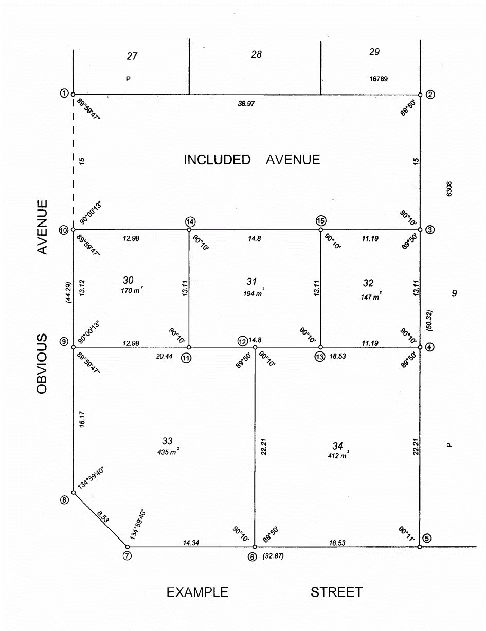
Figure 16.1: Point to Point Capture
3.2. Original Dimensions
As per example below:
- Original boundaries (lines) on Plans have attributes of ‘surveyed’ not ‘unsurveyed’
- Original angles and distances on Plans have attributes of ‘measured’ not ‘calculated’
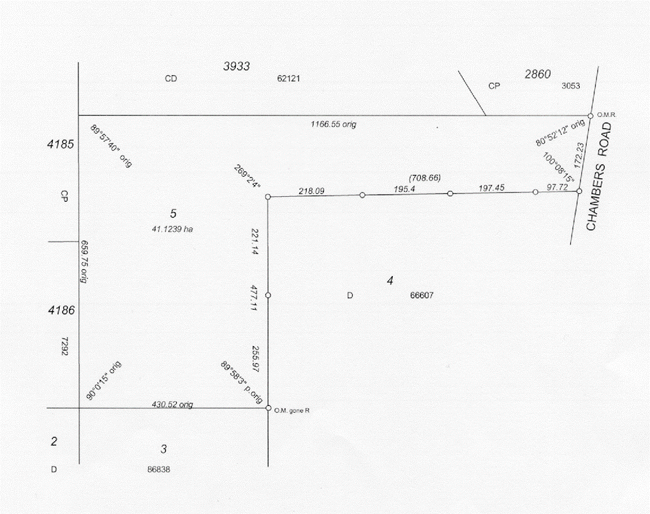
Figure 16.2: Original Dimensions
3.3. Easements, Covenants and Notifications
To assist in depicting easements and other spatial interests within Landgate’s spatial systems surveyors are requested to use the following procedures when capturing such polygons in CSD files:
- All Easement and portion only Covenant and Notification polygons burdening and benefiting land within cadastral lots depicted on a new Deposited Plan are to be captured in a CSD file using the polygon type ‘Easement’ or ‘Easement or Interest’ or ‘Interest’ depending on the version of the application used to create the CSD file.
- Easement points (e.g. points 7 to 14 inclusive, 13.8.14 in Figure 16-3) must now be intersected on cadastral boundaries when capturing the surround and lots (e.g. lots 500 & 501 on the sketch).
- The easement points for any new or existing easement must have attributes of ‘surveyed’ and have ‘Point Codes’ (i.e. ‘pnthormethod’ attribute) ‘T’, Traverse Adjustment, in the point records.
- The lines of all easement polygons (old or new) are to have attributes of ‘surveyed’ and have ‘Line Codes’ (i.e. ‘distderiv’ attribute) ‘M’, Measured.
- The ‘line type’ attributes used for lines of easement polygons are to be as follows:
- ’R’, Cadastral Road – where the easement line coincides with a road boundary (e.g. line 7-8 on the sketch).
- ‘I’, Cadastral Internal – where the easement line coincides with an internal cadastral boundary (e.g. lines 9-10, 11-5, 5-6, 13-5 & 14-6 on the sketch).
- ‘E’, Easement – where the easement line does not coincide with a cadastral boundary (e.g. line 14-13, 13-12, 12-11, 8-9 & 10-7 on the sketch).
- The ‘Angle Codes’ (i.e. the ‘angderiv’ attributes) for angles of all easement polygons (old or new) are to have attributes of ‘measured’.
- Where Deposited Plans are amended following lodgement at Landgate by the addition or deletion of easements, Landgate Officers will apply discretion on whether a replacement CSD file from the surveyor is required.
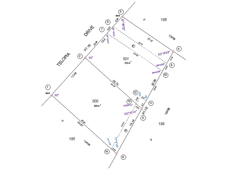
Figure 16.3: Easements, Covenants and Notifications
3.4. Interest Only Plans
To enable the correct positioning of the easement on the lodged layer, the CSD file must include at least 3 connections (angles and distances) between the easement and the cadastral corners (bends)
Figure 16.4 below illustrates the requirements. The connections 2-8 and 3-6 as well as 1-7 and 4-5 are required.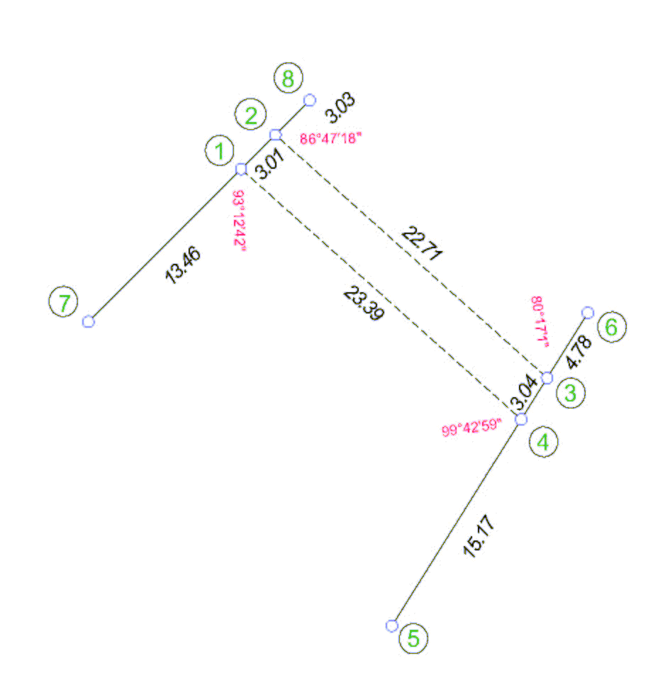
Figure 16.4: Interest Only Plans
3.5. Split Surrounds and Lots
Split surround polygons are to be captured as separate polygons linked by a traverse, both being labelled surround and are to be captured as separate polygons using same lot number, except when real world coordinates are used.
Capture Method (see Figure 16-5):
- Surround using points 1 to 7 inclusive.
- Traverse in points 3, 8 & 9 (to create a link to the separate polygon).
- Surround using points 9 to 13 inclusive.
- Lot 14 using points 1, 2, 3, 4 & 7.
- Lot 8 using points 4, 5, 6 & 7.
- Lot 14 using points 9 to 13 inclusive.
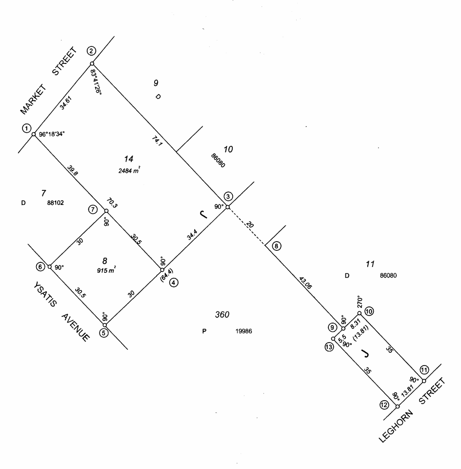
Figure 16.5: Split Surrounds and Lots
3.6. Tie to Existing Cadastral Corner
This allows accurate positioning of the survey.
Capture Method (see Figure 16-6):
- Surround using points 1 to 4 inclusive.
- Lot 723 using points 1 to 4 inclusive.
- Traverse to point 5.
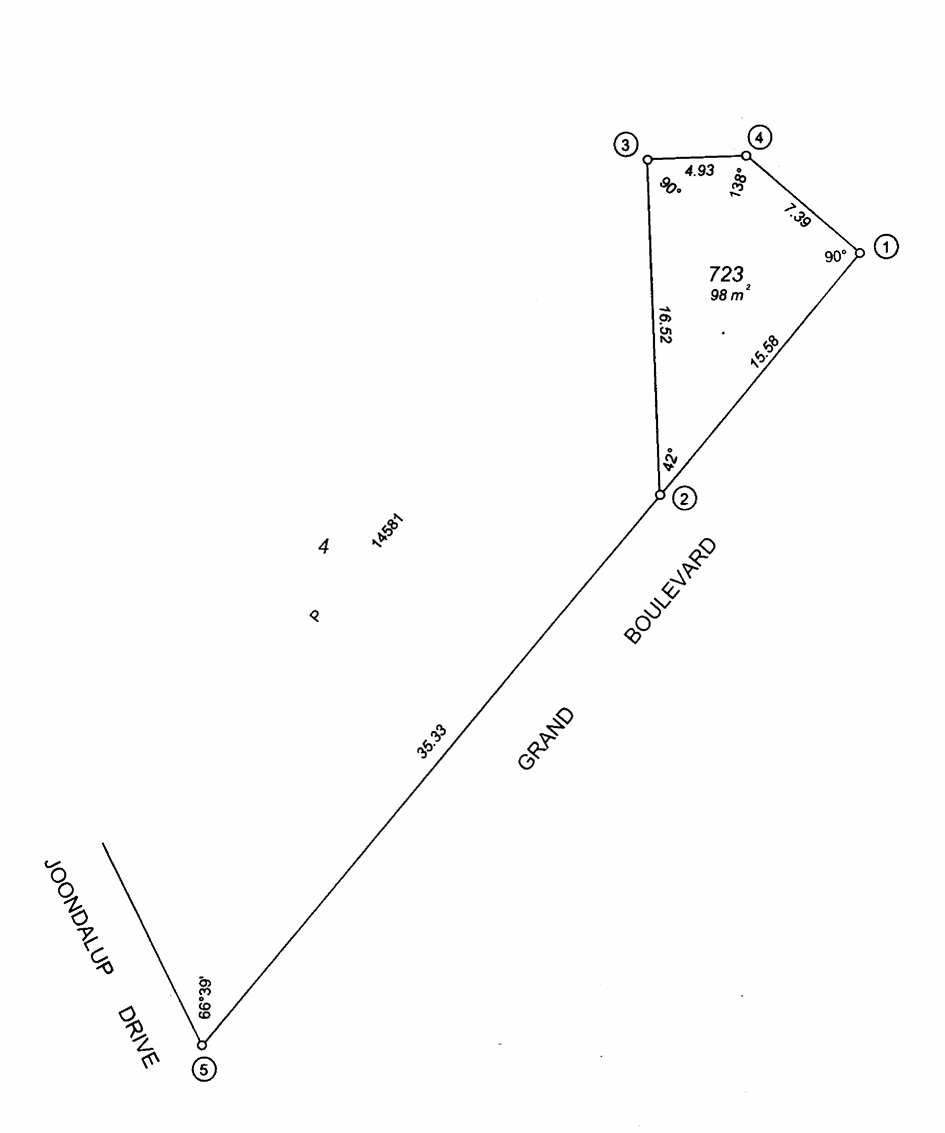
Figure 16.6: Tie to Existing Cadastral Corner
3.7. Water Feature (Topographic String)
Where a water boundary is not being defined by survey and it is the lot boundary the Topographic string is not required. Only show a construct line with angles, joining the end points and amend the area to agree with the Plan (being balance area of C/T).