This guide is intended as general information only. If you are uncertain of your rights or interests, please seek professional legal advice. Landgate staff are not able to give legal advice or to draft your documents. Please read our Terms of Use above.
Guide fully reviewed and rewritten 04/04/2023
2. Pre-Allocation of Plan and Field Record Numbers
4. Scale should be Suitable to Show Detail
10. Old Lines to Complete Surround
11. Connections Between Severances
15. Multiple Owner Subdivision
16. Freehold: Land Acquisitions
18. Rural Road Dedications and the Non-Extinguishment of Native Title
25. Truncations and Road Widenings
27. Subject Land Total Distance
29. Enlargements and Displaced Detail
35. Azimuths and Grid Bearings
36. Administrative Boundaries on Crown Plans
37. Permanent Improvements as Boundaries
38. Encroachments, Building Connections
39. Parcel Identifier within Subject
41. Unmarked Defined Boundaries
43. Depiction of Mineral Reservations
45. Lot Numbers for Vesting Lots and Land Acquisitions
46. Depiction of Original Unsurveyed Boundaries
1. Plan Forms
Plan form templates are available in the e-Plan Kit accessed via My Landgate Survey Channel. e-Plans are to be lodged in accordance with the e-Plan Guidelines in Appendix 6.
2. Pre-allocation of Plan and Field Record Numbers
Surveyors must obtain from Landgate pre-allocated numbers for Deposited Plans, Scheme Plans and field records. The numbers are only pre-allocated to a survey firm, not an individual surveyor.
To avoid or minimise enquiries being made at Landgate about unlodged Plans and/or field records using pre-allocated numbers, surveyors should indicate on any copy of a Plan provided to a client or conveyancer that the copy is an ‘unlodged version’.
Numbers will be pre-allocated to survey firms by applying to Landgate via email at planreg@landgate.wa.gov.au.
The subject heading of each email should be ‘Pre-allocated Numbers Request’.
3. Multiple Sheet Plans
Regulation 10 of the Transfer of Land (Surveys) Regulations 1995 limits the number of sheets in a deposited plan to 4 unless the Inspector of Plans and Surveys or an Authorised Land Officer approves a greater number of sheets.
The Inspector of Plans and Surveys has approved Deposited Plans with a purpose of ‘Subdivision’ to be comprised of an unlimited number of sheets. The principal criteria to use when preparing such Plans is the clarity and accuracy of the information depicted.
The recommended practice for depicting surveys on Plans involving more than two sheets is for the first graphics sheet to be an index to subsequent sheets.
Sheets should be individually numbered and cross-referenced to the other sheets for that Plan.
4. Scale should be Suitable to Show Detail
An appropriate metric representative fraction should be chosen and should be sufficiently large, such that when Plans are reduced to A4 size, all detail is clear and legible.
The preferred scales are:
1:750 1:1500 1:3000 1:6000
1:1000 1:2000 1:4000 1:8000
1:1250 1:2500 1:5000 1:10000
or multiples or divisions of 10 thereof.
It is preferred that enlargements are drawn at a larger scale but where this is not practicable the enlargement must be clearly annotated as being ‘NOT TO SCALE’.
5. Graphical (Bar) Scale
A graphical (bar) scale suitable for measuring distances on the Plan shall be shown on each graphics sheet. It is best practice to show the Bar Scale close to and under the Representative Fraction.
6. Orientation
The orientation of the Plan is to be indicated by a north point arrow which should be at least 100mm long.
All portal plans shall be oriented with north pointing to the top on all sheets.
For CAD plans, it is highly recommended that the Plan be oriented with north pointing to the top on all sheets.
However, the orientation may be rotated to incorporate a best scale for the shape of the subject land, if a ‘north up’ orientation will cause an excessive number of sheets to be drafted.
Survey Sheets shall be oriented the same as all other sheets of the plan.
The free text annotations must be inserted parallel to the bottom of the Plan regardless of the direction of the north point.
The north point should never point generally downwards.
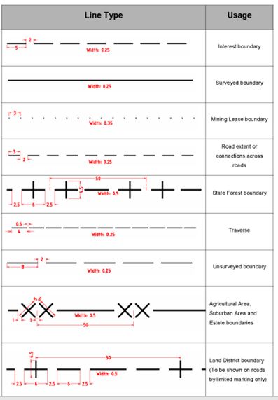
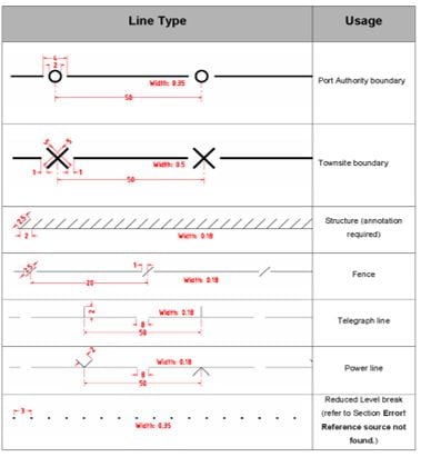
7. Line Styles
The Line Styles that should be used:
8. Text Styles
The text sizes and styles listed are those recommended to ensure readability of plans when photo-reduced, reproduced or faxed.
Test Sizes and Styles
The font used for these texts is to be of a type such that the first priority is optimum legibility of a reduced size copy. It should be an open style without serifs and with clear distinction between similar shaped figures and with a readily visible decimal point. The preferred font style is ISO 3098 or similar. Black text and line work only is to be used on Plans.
9. Symbols
Refer to regulation 51 of the Licensed Surveyors (Transfer of Land Act 1893) Regulations 1961 for symbols and annotation concerning posts, pegs and intermediate marks.
Where marks are gone and it is not possible to place a mark at the original position (that is, the new mark is offset from the original position), then the mark is shown as MG or OMG- not MGR or OMGR.
The survey type when a mark is originally placed determines the annotation from then on. Marks placed at corners created by Crown surveys will always be either OM, OMR, OMG or OMGR regardless of whether they are replaced by a freehold survey.
Similarly, corners originally marked during a freehold survey will always be MF etc.
In rural surveys mileposts and kilometre posts shall be shown as a double circle and the notation 1 MP, 1 KMP or if found or replaced 1 MPF, 1 KMPF, 1 MPR, 1 KMPR. (See plan example 29.)
10. Old Lines to Complete Surround
Where existing angles and distances are used to complete the surround of a survey, dimensions from the latest existing surveys should be used.
In some cases, information from field records can be used where it is clearly proven and differs considerably from original surveys. The new field record must refer to the original field records adopted for the surround dimensions.
Where angles and complete distances are shown, these shall be labelled ‘orig’ and no existing intermediate distances and marks shall be shown.
It is not necessary to include the ‘orig’ labelling on deposited plans for Special Survey Area subdivisions provided the surveys have been carried out by the same survey firm.
If the surround or part of the surround of a Special Survey Area subdivision is measured by a different survey firm, the ‘orig’ labelling must be used
The surround field records must be shown in the ‘Field Records’ field on the Plan.
Where a line is comprised of both existing and new work, the existing portion is labelled ‘orig’ and is shown without intermediate distances and marks. The total distance should be labelled ‘per orig’ (as should any angles and distances calculated from a combination of existing and new measurements).
Circles (indicating survey pegs or posts) should not be shown at original lot corners unless marks were found at those corners. Corners not marked should be shown without a circle.
CSD files need to supply ‘relativity’ between any severances captured unless real world coordinates are provided. This could be achieved by a traverse through cadastral alignments or a single calculated tie.
11. Connections between Severances
Where practicable, connections between severances should be shown on Deposited Plans.
Ideally, severances should have separate lot numbers, but this may not always be possible.
The position of parcel severances is defined by the abuttals. Any connections between severances shown on a Plan are of secondary importance to the abuttals.
12. Measurement Content
The total length of each individual lot boundary line must be shown on the plan.
Distances to and between intermediate marks must be shown.
Intermediate distances must be rounded such that they sum to the total distance, which is the total measured distance.
13. Measurement Presentation
Distances shall be shown in metres to the nearest 0.01 metre.
Refer to the SSA Guidelines for treatment of distances on Survey Sheets.
For distances less than one metre, the decimal point shall be preceded by a ‘0’ (e.g. 0.75 not .75).
‘0’ need not be shown as the last character of a distance to the right of the decimal point (e.g.15.10 is expressed as 15.1).
Angles shall be shown to the nearest second.
Zero seconds or zero minutes and seconds need not be shown (e.g. 170°0’0” is expressed as 170° and 170°11’0” is expressed as 170°11’).
See Section 27 for the presentation of areas.
14. Balance Lots
Regulation 5(1) to (3) of the Transfer of Land (Surveys) Regulations 1995 requires surveyors to include in plans of subdivision, acquisition and amalgamation (this includes amalgamations of Crown land with freehold land) any residue land as a separate lot or lots. See plan examples 2, 11 and 53.
Where a road has an existing lot number and a portion is to be closed, a balance lot must be created showing any existing interests carried forward. The heading to include:
‘and Dedicated Roads (Lot 300)’.
See plan example 85.
Sub-regulation (5) states that if the boundaries of the residue are extensive the Registrar of Titles, Inspector of Plans and Surveys or an Authorised Land Officer (ALO) may allow the part of the Plan showing the residue to be compiled and the distances, angles or bearings (where applicable) for the boundaries, easements or covenants to be omitted.
Sub-regulation (6) states that the Registrar of Titles or an ALO may direct that sub-regulations (1) to (5) do not apply to a particular Plan of Crown Land. Such situations will most likely occur where UCL, Pastoral leases, State Forests and large reserves are involved.
Formal applications for an exemption under regulations 5(5) and 5(6) are necessary. (See plan example 100.) The approval of either the Registrar of Titles, Inspector of Plans and Surveys or an ALO as the case requires must be obtained before these exemptions can be used.
Surveyors shall identify any balance lots that are not to receive servicing facilities, by using a lot number in the 9000 number range.
Any ‘super lots’ that are the subject of future stages in the subdivision must be identified using the 9500 number range.
These number ranges indicate to the planning authorities that subdivisional conditions relating to the utility servicing and land access will not generally apply to these lots.
Where a large balance lot has many abutting lots and roads such that it is difficult to show all the abutting lot numbers and road names at a suitable scale, the abuttals may be depicted by line-work and references to the relevant plan numbers only.
15. Multiple Owner Subdivision
Plans involving multiple owners will require all the relevant transfer documents and consents pertaining to encumbrances to be lodged before the Plan is approved.
New Titles will be issued in accordance with a single application (signed by all the affected owners).
The ‘former tenure table’ shall clearly show the previous tenure of each new lot. (See SPP-10 Plan Practices Section 7) to assist the preparation of the conveyancing documentation and new title creation.
16. Freehold: Land Acquisitions
Where an acquiring authority has reached agreement with the affected registered proprietors, the process can be treated in a similar manner to a normal subdivision.
The Plan shall show the complete details of the residue parcels which shall be given a new parcel identifier.
The application for New Titles, including the Titles of the residue lots, shall contain the signatures of all the registered proprietors of the subject land.
The acquired lots then transfer to the acquiring authority or the ‘State of Western Australia’.
If the acquired land is to be a road, another option is a road dedication.
It may be possible to allocate only one lot number to the whole of the acquired land, in which case the taking orders shall refer to the relevant portions of the lot.
No partial approvals are permitted with acquisition Plans affecting Freehold Land– the application for New Titles shall include all lots shown on the Plan.
Where an acquiring authority is unable to reach agreement with the registered proprietors, the registration of a ‘Notice of Intention to Take’ against the affected Title is required.
The registration of a ‘Taking Order’ will cause the issue of New Titles to the acquiring authority for the acquired land.
The ‘Taking Order’ will also trigger the ‘automatic’ creation of any balance Titles. No sundry documents are required.
It is not possible to show sole subject road dedications on Survey Plans where a residue (i.e. part lot) is created.
Such dedications shall be carried out in the same manner as a normal subdivision with the residue land being allocated a unique parcel identifier.
Section 168(5) P & D Act can be used for sole subject road dedications where the subject is a whole lot or all of an existing part lot.
See plan examples 5, 11, 85, 95 and 102.
See also see SPP-11 Specific Plan Purposes Section 1.
17. Crown Land Acquisitions
A Crown Plan type must be used where Crown Land is involved and it is intended that the land acquisition lead to road dedication or Crown easement creation.
In this case, there is a requirement for a Crown Land Title to be prepared for registration of the ‘Notice of Intention to Take’ and the ‘Taking Order’.
Where Native Title rights exist, staged plan approval may be required.
See plan examples 54, 61, 70, 71, 100 and 104.
18. Rural Road Dedications and the Non-Extinguishment of Native Title
Section K of the Native Title Act 1993 (Cth) NTA) deals with the provision of facilities to the public and allows for the non-extinguishment of Native Title.
In accordance with a Government Task Force’s recommendations, Section K of the NTA and the non-extinguishment principle is applied to many rural road dedications.
This means that Native Title exists during the currency of a rural road dedication, but is suppressed whilst the road remains dedicated and the public has the right to use the road.
Relevant authorities can maintain the road.
Native Title re-asserts itself and takes precedence when the road, or a portion of it, is closed, and the land reverts to being Unallocated Crown Land.
Plan examples 104 and 105 indicate how the non-extinguishment principle is to be depicted on deposited plans within the Interests and Notifications schedule.
Specific Native Title holders shall be shown in the ‘Benefit To’ column.
19. Adverse Possession Claims
The plans for Possessory Title applications (see SPP-15 Possessory Applications and Bringing Land under the TLA) need to be prepared in the same manner as multiple owner subdivisions with all portions of land uniquely identified on one Plan.
As the landowner adversely affected by a successful claim is unlikely to sign any documentation, balance Titles automatically issue on registration of a sundry document or on direction from the Commissioner of Titles.
Refer to STP-18 Adverse Possession and Strata Titles for when a successful claim adversely affects a Strata/Survey-Strata Scheme.
20. Isolated Crown Surveys
The Registrar of Titles or an Authorised Land Officer may authorise for an isolated Crown parcel to be shown on a Plan without the residue land being shown on the plan. (See Section 15 Balance Lots.)
Plans of isolated parcels that are not connected to the State Geodetic Network must show bearings and an azimuth source.
21. Residue Land Solutions
There are some situations where the depiction and/or definition of residue land in a subdivision results in difficulties for surveyors. The following should assist surveyors in dealing with most of the difficult situations that are likely to occur.
21.1. Multiple Lot Titles
Surveyors and landowners/developers should note that the following options are currently available when undertaking subdivisions or acquisitions of land held in multiple lot titles:
21.1.1.
In the case of a subdivision, the landowner/developer may elect to have the residue land shown on the plan as a new single balance lot. This option is not currently available for a proposed acquisition for public purposes.
21.1.2.
Alternatively, the landowner/developer may opt to apply for separate Titles or a single balance title for the residue land.
21.1.3.
A Plan may be lodged where the former tenure includes a whole individual lot (or lots) within a multi-lot Title (i.e. does not cover all lots contained in the Title). Any remaining original lots will continue to exist on a multi lot title.
21.1.4.
For acquisitions/takings under the LAA this may be achieved by a sundry document. The former tenure table on the Deposited Plan must clearly show that only a ‘part’ of the multi-lot Title is included in the Plan. A further sundry document may be required following registration of the taking to create a balance of the multi-lot Title.
21.1.5.
In some situations involving acquisitions/takings under the LAA, it may be more practicable for Landgate to partially cancel the multi lot Title. In these situations, Regulation 5(6) of the Transfer of Land (Surveys) Regulations 1995 will apply and no residue land is to be depicted on the acquisition Plan. See plan example 85.
21.2. Possessory Applications Claiming Part of a Multiple Lot Titles
Where a possessory application is lodged claiming part of the land contained in a multiple lot Title, the resultant Deposited Plan must show the residue of any affected lots as new lots.
Lots not affected by the claim should not be depicted on the Deposited Plan.
The former tenure table on the Deposited Plan must clearly show that only a ‘part’ of the multi-lot Title is included in the Plan.
Landgate will register a sundry document following registration of the possessory application to include the unaffected lots and the new balance lots from the old multi-lot Title in a new multi-lot Title.
21.3. Road and Road Widenings from Extensive Freehold Parcels
Where a road or road widening is proposed to be acquired from an extensive Freehold parcel such as a golf course, an application in writing may be made to the Registrar of Titles to utilise regulation 5(6) of the Transfer of Land (Surveys) Regulations 1995. If the application is approved, no residue land needs to be depicted on the Acquisition Plan. (See plan example 85.)
The Plan is to be annotated ‘Lot ____ to be acquired under Part 9 of the LAA is Crown land for the purposes of Transfer of Land (Surveys) Reg 5(6)’.
21.4. Excisions from Corridors
Where a new development requires an excision from a road, railway, drain or similar infrastructure corridor for which no Title exists, it is not necessary to show the residue of land in the corridor on the new Deposited Plan depicting that development.
If an excision occurs from an extensive road, railway, private Right of Way, drain or similar corridor, that is held in a paper Certificate of Title early contact with the Inspector of Plans and Surveys at Landgate must be made to allow an assessment on whether a balance lot for the residue land is required.
Some of the options available in such situations include:
21.4.1.
Landgate resolving the situation by amending the original Plan by allocating a ‘lot on plan’ identifier to a manageable portion of the corridor (usually a portion within a street section).
21.4.2.
Landgate preparing a new graphic to allow digital Titles to capture the corridor or part of the corridor, in manageable portions.
21.4.3.
In rare cases, it may be more practicable for Landgate to maintain the paper Title and the relevant graphic. In these situations, regulation 5(5) of the Transfer of Land (Surveys) Regulations 1995 will apply and the new Deposited Plan is to contain an annotation stating that the residue land in the Title for the corridor is not fully depicted on the Plan.
22. Road Widths
Road widths within the Plan must be shown. See SPP-13 Roads Section 13.
For Crown Grant roads, see SPP-13 Roads Section 14.
23. Road Names
Any roads created on a Plan require a name approved by Landgate under Sections 26 and 26A of the LAA on behalf of the Minister for Lands.
This approved name should be shown on the Plan and in relevant field records.
Refer also to Policies and Standards for Geographical Naming in Western Australia.
New road names require the endorsement of the relevant local government, and it is essential that the names are proposed early in the land development process and conform to the Policies and Standards to avoid delays in the approval process.
The extent of road names for both newly created roads and existing roads must be easily recognised on the face of the Plan. See plan example 53.
All lodging parties are required to include all relevant road Approval documents at the time of lodgement of the Plan where the Plan contains a new Road or Road Extension. The road name Approval must match the design layout as Approved by Geographic Names.
Names and layout of existing Approved roads should be obtained from Map Viewer Plus. If there is conflict or uncertainty regarding road names, contact Geographic Names.
Where a previously dedicated road is being defined by survey, the heading of the Plan is to include:
“& DEDICATED ROAD”
24. Connections across Roads
Connections across roads, consisting of an angle from an alignment and the distance across the road, must be recorded on the plan at each angle point; at a suitable scale, using enlargements and additional sheets as necessary for clarity.
It is acceptable to omit the half angles in the case of parallel road alignments. Connections between the angle points of a series of shorter boundaries that comprise the sides of a parallel road in a town or suburban subdivision may be omitted such that there is no more than 50 metres between connections, and providing that there is a connection across the road at the end of each straight section longer than 50 metres.
These distances may be extended to 100 metres for rural and rural-residential subdivisions.
25. Truncations and Road Widenings
Regular and irregular truncations (i.e. unequal set back distances) on a Plan of subdivision must be labelled ‘ROAD WIDENING’. If the road widening does not automatically dedicate, a parcel identifier (i.e. Lot Number) must be added.
Land for the purpose of adding to a public street or road is to be labelled ‘ROAD WIDENING’. See plan example 56.
26. Areas
For areas less than 10,000 square metres area is shown to the nearest square metre (e.g. 9446 m²).
For areas of 10,000 square metres or greater, area is shown in hectares to four decimal places (e.g. 9.2713 ha).
‘0’ need not be shown as the last character of an area to the right of the decimal point (e.g. 6.4500 ha to be shown as 6.45 ha).
Areas are to be shown for each distinct parcel of land shown on the Plan with the exception of roads that automatically dedicate under section 168(1), (2) of the P & D Act and areas are to be shown for all road widenings that automatically dedicate under section 168(3) of the P & D Act and section 28(1) of the LAA.
27. Subject Land Total Distance
A distance may be shown along each external boundary of the subject land to define the extent of the subject land.
The distance shall be placed in parentheses if the subject land total distance is the sum of two or more land parcels.
28. Abuttals
All lots abutting the land the subject of the Plan for which certificates of title have issued at the time of lodgement of that Plan shall be identified by their lot on Plan numbers.
Where a large balance lot has many abutting lots and roads such that it is difficult to show all the abutting lot numbers and road names at a suitable scale, the abuttals may be depicted by line-work and references to the relevant Plan numbers only.
Lots on Plans that have been lodged but not yet approved (shown on the “lodged layer” within the SCDB) must not be shown as abuttals unless sound knowledge is demonstrated by the surveyor that lodgement of dealings for those lodged Plans is imminent. This will usually only apply when the surveyor who certified the ‘lodged layer plan’ is the same, or from the same firm, as the surveyor lodging the current plan.
Freehold Plan numbers are to be prefixed by either ‘P’ or ‘DP’ as appropriate. Freehold diagrams lodged prior to 1 July 2000 are to be numbered with a prefix ‘D’ and Scheme Plans as ‘SP’. Dual-numbered Crown plans and diagrams are to be shown as their DP number only.
Where the duplicates (“mini-plans”) of subdivisional Plans were drafted as multiple sheets for convenience, Plan sheet numbers need not be shown.
If the original Plan is a multi-sheet ‘Deposited Plan’ using the new Plan format, the sheet number should not be included.
The numbers of all adjoining Crown reserves should be shown.
Note
For abutting private rights of way and private roads, see SPP-14 Easements, Covenants, Notifications and Other Interests Section 6.
If an abutting road is necessary for access into the subject Plan, then the name of that abutting road shall be shown on the subject Plan, and the subject Plan will be made In Order for Dealings subject to the approval of that abutting Plan if it is not already approved.
In many country townsites, for example Kalgoorlie, there are many public undesignated accessways created on Crown Plans and Diagrams. These are shown with the DP number and designated ‘Public ROW’ in brackets.
When a lot abuts a public or private road, ROW, PAW (even 0.1 metre wide), drain reserve or waterway, the extent and location of that abuttal is important to the proprietor. The information is usually provided incidentally by the dimensions of the subject lot and the placement of the name or description of the abuttal.
In those infrequent cases where an abutting public or private road, ROW, PAW, drain reserve or waterway is not located exactly by other dimensions, sufficient extra external surround dimensions should be added to the Plan to indicate the position and extent of that abuttal.
Where main roads or highways are abuttals, the notation ‘Proclaimed Highway’ or ‘Main Road under the Main Roads Act’ is to be shown with the Plan number and a lot identifier if there is one. If the highway has a name, it should also be shown. Typical examples of these highways are Tonkin, Roe, Reid and the Bunbury-Busselton Bypass. Some of these roads are not dedicated and remain under the TLA where the Crown or the Commissioner of Main Roads are the registered proprietors.
Sections 13, 14 and 28A of the Main Roads Act 1930 are relevant to the proclamation of highways and main roads, and the control of access to them.
Abutting railway reserves (Crown or Freehold) are shown with the Plan number and labelled ‘RAILWAY’.
Abutting drain reserves (Crown or Freehold) are shown with the Plan number and labelled ‘DRAIN’.
Where an abuttal is the subject of a Strata Titles or Community Titles Scheme; the Scheme Plan number should be placed (in brackets and prefixed) under the DP number under the parent lot number for the abuttal.
28.1. Depiction of Part Lots as Abuttals
To allow most of the existing lots described as part lots (as a result of road excisions etc.) to be captured as digital Titles, it was necessary for them to be captured as whole lot Titles endorsed with an exclusion notation (e.g. excludes road shown on CP1234). These same lots were also all converted in the spatial database to be shown as whole lots.
New Deposited Plans should show these lots (i.e. former part lots that have been captured as whole lots), as whole lots, where they exist as abuttals.
28.2. Dual Numbering of Crown Plans and Diagrams
To enable Freehold Titles that exist over lots/locations depicted on the various types of Crown Plans and Diagrams to be captured in the registrations system, it has been necessary for Landgate to allocate them a Deposited Plan (DP) number. The table in SPP-02 Searching Landgate Records Section 5 indicates the number ranges allocated to each Plan or Diagram type.
Dual-numbered Crown Plans and Diagrams are to be shown as their DP number only.
29. Enlargement of Displaced Detail
To maintain clarity or overcome a lack of space, enlargements or arrowing in detail may be used.
The arrowed in, displaced detail should be parallel to the line in the case of a linear measure and on the half angle in the case of an angular measure.
Enlargements need not be drawn to scale.
Ambiguous labelling of enlargements is to be avoided.
If other components in a plan (e.g. easements, cross-sections or access restrictions) require labelling, different letters of the alphabet should be used.
It is often required to depict a parcel at the end of a long traverse in remote areas. In such cases, the entire survey at scale (parcel and traverse) is to be depicted with suitable enlargements for the parcel.
Insets are usually required for:
- Lands for Revestment
- Crown Land Amalgamations
- Closed Roads within the subject
Easements over Crown Land for inclusion.
30. Water Features
Where lines of coasts, rivers, lakes, swamps or watercourses form part of the boundary to a lot, these should be shown by full black lines and suitably named where appropriate. See plan examples 9, 57 and 59.
A notation to be used for when HWM is the boundary is as follows:
‘Reference to 'high water mark (HWM)' means as defined in the Land Administration Act 1997’.
Both sides of non-tidal watercourses should be shown where practicable and an arrow denoting the direction of flow of the stream.
Showing a water boundary as an abuttal requires an annotation as to the nature of the boundary definition e.g., ‘HWM’, ‘Boundary is low water mark’ or ‘not a riparian boundary’.
If any ambiguity exists or boundaries are determined from aerial photography then an annotation should be used (e.g. in the case of a retaining wall, ‘High Water Mark’ or in the case of aerial photography ‘HWM drawn from 2022 aerial photography’).
If inconsistencies in the boundary definition are found, the situation should be resolved with the Inspector of Plans and Surveys before lodgement.
When tidal boundaries are located on the ground by setting out a contour at a height above AHD calculated to be at the definition of HWM; those boundaries on the plan should carry the annotation- ‘High Water Mark (at.......m above AHD)’, quoting the actual height adopted above the Australian Height Datum.
Refer SPP-05 Surveys of Water Boundaries for information on surveys of water boundaries.
31. Colouring
The colouring required on both Crown and Freehold Plans is as follows:
- A green border is to be shown along the boundaries of the subject land.
- New section 167 of the P & D Act easements in favour of a local government are uncoloured.
- New section 167 of the P & D Act easements in favour of the Water Corporation are uncoloured.
- New section 167 of the P & D Act easements in favour of the holder of a gas distribution license (such as Alinta Gas) or Electricity Generation Corporation, Electricity Networks Corporation, Electricity Retail Corporation, Regional Power Corporation are uncoloured.
New roads within the subject land, pedestrian accesses, both private and public ROWs, abutting vested PAWs and ROWs, abutting private ROWs, abutting public road and public ROWs (those created on a Crown survey Plan/diagram), abutting Crown reserves, abutting railway reserves, abutting drain reserves, water features and abutting State forests are all to be left uncoloured. Full descriptions of private road abuttals are required in lieu of colouring. (See Section 22.)
32. Fixation of Surveys
The Plan of an isolated survey must show a connection or tie to an existing cadastral boundary so that the survey can be located in relation to the existing cadastre.
To help locate surveys, it may be useful on to show connections to nearby road intersections or other distinctive survey features.
33. Lot Number Duplication
See SPP-21 Subdivision and Project Management Issues Section 9.
34. SSM Depiction
On rural Crown surveys, all SSMs connected to must be shown on the Plan.
For GNSS surveys, the calculated mid-azimuth derived from the GNSS observation shall be shown to the nearest second.
Coordinates of SSMs are not to be shown.
The only information to be shown is the SSM name.
See plan example 64.
35. Azimuths and Grid Bearings
Azimuths or Grid Bearings need only be shown on Plans when specific guidelines for a type of survey require that they be shown (e.g. Isolated Crown Surveys, Road Casement Surveys).
The source of any adopted azimuth or bearing shown on Plans is to be included in the graphic area of the Plan form. Examples of possible sources include:
- an existing Plan or diagram,
- an observation for azimuth (astronomic or GPS),
- geodetic connection, and
- the SCDB (include date of download/enquiry).
36. Administrative Boundaries on Crown Plans
The following administrative boundaries are to be shown on Crown survey Plans:
36.1. Townsite Boundaries
Townsites were created by both the former Land Act 1933 (LA) and by the Local Government Act 1960 (LGA).
All LGA townsites became LA townsites upon proclamation of the Local Government
Act 1995.
Section 26 of the Land Administration Act 1997 is now the head of power for townsites.
36.2. State Forest Boundaries
When creating:
- Lots ex State Forest - boundaries to be shown around the subject ceasing at road (indicating that State Forest also exists on the other side of road).
- Roads (sole subject) through State Forest - no boundary to be shown.
- Roads (sole subject) with one State Forest boundary - boundary to be shown.
Note:
The depiction of a State Forest boundary must indicate one side of the boundary is State Forest.
36.3. Other Administrative Boundaries
Agricultural Area, Suburban Area and Estate Area boundaries may be shown.
Port Authority Boundary must be shown.
Local Government boundaries (only for Road Casement Surveys by Limited Marking – regulation 26A as issued by Main Roads WA).
Note:
Refer Section 9 for line styles.
37. Permanent Improvements as Boundaries
When permanent improvements are intended to form a boundary (e.g. building or fence line) then graphic depiction of that improvement is required along with detail of corner definition.
38. Encroachments, Building Connections
If part of a building, wall or other significant improvement is built such that it crosses over the boundary between the subject land and an abutting lot, the encroachment must be recorded on the plan. Connections to buildings, walls and other types of significant improvements that are close to, but do not cross over, the boundary of the subject land may be recorded on the plan at the surveyor’s discretion.
39. Parcel Identifier within Subject
Wherever possible the Parcel Identifier is to be shown within the subject and orientated parallel to the base of the Plan.
If the subject land comprises a reserve, the reserve number is to be shown unless it is known that the subject land is to be removed from the reserve, or the reserve is to be cancelled, during the dealing of the Plan.
40. Pastoral Leases
A broken station name is to be shown e.g. ‘IDA VALLEY STATION’ along with any current lot numbers.
Connections must be shown to the nearest pastoral lease boundary from any surrenders/excisions.
41. Unmarked Defined Boundaries
Boundaries which have been spatially determined but which have not been fully marked will be symbolised by an unbroken line.
A description of the approval pursuant to either general regulation Reg 26A or Land Administration regulation 21(1) shall be shown within the ‘Survey and Plan Notation field.
Examples of these are:
- surveys using GNSS methods, providing monuments and/or DRMs have been placed at each corner
- road surveys through State Forest and timber reserves, where the boundaries have only been partially marked
- road surveys where one boundary has been marked by traditional methods with the opposite side being calculated
- boundaries with distances between intermediate marks exceeding 250 metres
- limited marking road casement surveys. See plan examples 70 and 71.
In all these cases, the boundary dimensions are accurately determined by survey and can be accurately fixed on the ground in the future.
Boundaries that have no mathematical or spatial integrity and have not been surveyed can be shown on certain Crown Plans by a broken line; usually where the land is not to be alienated.
Additionally, unmarked boundaries of very large parcels that are defined by geographical coordinates and long connections from existing geodetic survey marks should be shown with broken lines to indicate that a survey specifically for defining those boundaries has not been carried out.
The geodetic datums shall always be stated when providing a set of coordinates and/or height.
See Section 47 below for the depiction of ‘Sketch on Transfer’ boundaries and boundaries created from subdivisions by description.
42. Compiled Plans
Compiled Plans may be used in some situations pursuant to regulation 4 of the Transfer of Land (Surveys) Regulations 1995.
It can be applicable to cases where the boundaries of the subject land have previously been defined by approved Plans, cancelled surveys, superseded surveys, lodged field records and Plans certified correct but not yet dealt on.
Surveyors are reminded of the strict procedural guidelines associated with the use of Operational Directives such as Executive Minutes 10/92, 17/90 and Survey Registration Minute 1/98, when creating Complied Plans.
Any enquiries regarding these directives are to be referred to the Inspector of Plans and Surveys.
See APX-02 Operational Directives and plan examples 58, 66 and 67.
Angles and distances used in the compilation are derived from the best available information for the subject land boundaries.
The information is to be obtained from the latest measurements shown on both Crown and Freehold Plans, either parent Plans or abutting Plans, for either part or all of an existing boundary; and also plans of mining tenements where appropriate.
In the case of sketch on transfer boundaries, the title distance is used in the compilation.
Where imperial distances have been metricated on the working copies (duplicates) of Plans and diagrams, for example, 100 links and 90 links, which convert to 20.117 and 18.105 respectively, they are shown as 20.12 and 18.11 respectively on the “duplicates”. An amalgamation of lots with these distances would give a total imperial distance of 190 links which, when metricated, gives a total distance of 38.22 metres, and not the 38.23 metres obtained from a sum of the metricated values. So, when compiling from imperial surveys add the required imperial distances to give a total and then convert that total to metric. In some cases it may require the field record to be searched to determine the correct dimensions.
On older Crown Plans the practice was to round off the total boundary distance to the nearest link. In these cases, Title distances take precedence.
The exception to this rule is when the shape of the original Title is changing by compilation of a couple of lots. In this case use the original measured distance before the rounding.
Field record values may be used on the compiled plan in some situations (e.g. in the case of excessive miscloses or where a repeg field record provides more accurate values than the latest original plan or diagram).
Boundaries for compiled lots (other than those created by a freehold subdivision) may be calculated (see plan example 8) providing:
- the calculated boundary is less than 250 metres in length (i.e. does not require an intermediate mark),
- the calculated boundary is between two previously marked corners or bends of parcels with live titles, and
- a site inspection has been made to ensure that there is no conflict caused by the proposed boundary position and that the new boundary can be identified by the proprietor.
Compiled plans cannot be used to re-instate boundaries that have been extinguished by an amalgamation or re-subdivision.
“Boundary lines” that were surveyed in the past, but which have not been used to define land boundaries, must be re-surveyed for them to become boundaries again – see as follows for an example of such a situation:
Where a distance on a compiled Plan comprises partly calculated/about and partly surveyed components, the separate components must be shown along with a ‘cal’/’abt’ total distance.
As a compiled Plan does not involve a survey, all the angles and distances are original.
By convention the suffix ‘ORIG’ should not be shown on any dimension.
Survey marks and intermediate distances are not shown.
A notation stating the Plans/diagrams, Certificate of Title, survey graphic, field record or other sources from which the compilation was derived is required.
Circles (indicating survey pegs or posts) should not be shown at lot corners on compiled plans.
The ‘Field Records’ field in the Survey Details section on the plan ‘administration sheet’ heading shall show the notation ‘COMPILED’ to indicate a compiled Plan.
For the preparation of compiled Plans within the CBD areas of Perth, West Perth and Fremantle see SPP-02 Searching Landgate Records.
43. Depiction of Mineral Reservations
The following outlines the requirements for the depiction of mineral reservations affecting land.
43.1. Reservations in Crown Grants
Mineral reservations contained in the original Crown Grants need not be depicted or recorded on Deposited Plans.
Each digital Title contains a prefatory statement that indicates that the land in the Title is ‘subject to the reservations, conditions and depth limits contained in the original grant’.
43.2. Lands Affected by Section 15 of the Public Works Act 1902
Prior to 1953, section 15 of the Public Works Act 1902 excluded from resumptions all minerals except those necessary for the construction, support and maintenance of public works.
Where minerals had been alienated and the land resumed, an undefined portion of the minerals remained unresumed, causing problems for the then Titles Office determining what had and what had not been resumed.
Crown Grants issued after the introduction of the Land Act 1898 had all minerals reserved to the Crown, making the situation clear from then.
The earlier grants of land (including grants under the Deeds Office system) prior to 1898, where portion of the minerals were alienated, remained a problem until in 1953 section 15 of the Public Works Act 1902 was amended to retrospectively provide that all minerals were included in any resumptions.
Section 15 was repealed in 1997 and replaced by section 164 of the LAA.
Titles to land affected by this provision will show different endorsements depending on the circumstances involved.
If the whole of the land is affected the endorsement may state; ‘save and except the rights to mines of coal or other minerals’, or ‘the right to mines of coal or other minerals being excluded from the said land’.
If portion of the land in a Title is affected the endorsement will usually state; ‘the right to mines of coal or other minerals being excluded from portion of the said land’.
In the past, areas affected by section 15 of the Public Works Act 1902 were indicated on the ‘working copy’ Plans (i.e. mini Plans and duplicate diagrams).
Landgate’s imaging system provides copies of the working Plans. These Plans are no longer produced by Landgate and it is now necessary to show the affected areas on Deposited Plans.
Working copy Plans indicate affected areas in one of two ways. The affected areas are hachured and the Plan annotated ‘Portion hachured subject to section 15 of the Public Works Act 1902’. In some cases, the unaffected areas are hachured and the plan annotated ‘save and except the portion hachured subject to section 15 of the Public Works Act 1902’.
Some roads closed and amalgamated under the former Road Districts Act 1919 were also subject to mineral reservations and are shown on ‘working copy’ Plans as affected by section 15 of the Public Works Act 1902.
Roads closed and amalgamated under the Land Act 1933 or the LAA are not affected by the provisions of section 15 of the Public Works Act 1902.
Where land affected by section 15 of the Public Works Act 1902 has been revested in the Crown, the provision no longer applies to the land revested. Lots that are revested are identifiable on the existing ‘working copy’ Plans by a ‘Revested’ notation or a change in the parcel identifier (lot number) to a Crown allotment.
If all the land in a new Deposited Plan is affected by section 15 of the Public Works Act 1902 there is no need to show on the Plan that the lots are subject to mineral reservations as this will be carried forward onto any new Titles created.
Where a portion of the land in a new Deposited Plan is affected by the former section 15 of the Public Works Act 1902 the Plan must show the subject portion and the Schedule of Interests and Notifications must indicate the new lots affected. See plan example 18.
In general, surveyors must bring forward onto new Deposited Plans the mineral reservations depicted on the ‘working copy’ Plans.
Portions of land affected by section 15 of the Public Works Act 1902 are usually not dimensioned on Titles or working Plans.
Surveyors are only required to plot affected portions on new Plans by scaling distances from existing documents and using labels, line-work and, where necessary, hachuring to clearly show the relevant portions. There is no need to include the information in CSD files.
43.3. Mineral Reservations in Transfers
Crown Grants that were registered in the name of the Commonwealth of Australia did not contain any mineral reservations.
Where the Commonwealth disposed of land, the transfer effecting the sale normally contained the same mineral reservations as contained in a normal Crown Grant.
Following registration of the transfer, the Commonwealth would then transfer to the Crown in right of the State the reserved mineral rights.
By virtue of the Midland Railway Company Acquisition Act 1963, the Minister for Western Australian Government Railways acquired all the property of the Midland Railway Company. The mineral rights granted or alienated to the Midland Railway Company become the property of the Crown on production of a vesting application by the Minister to the Registrar of Titles. Titles are usually endorsed ‘except and reserving metals minerals gems and mineral oil specified in Transfer No’ or ‘save and except minerals vested in the Crown pursuant to the provisions of section 4(5) of the Government Railways Act 54 of 1965. A Title may or may not make reference to the relevant transfer document.
Where portion of the land in a new Deposited Plan is affected by a mineral reservation contained in a transfer or vesting under section 4(5) of the Government Railways Act 54 of 1965, the portion so affected must be depicted on the Plan in a similar manner to that required for land affected by section 15 of the Public Works Act 1902.
Plan examples 8 and 30 indicate the requirements for bringing forward mineral reservations created in transfers
44. Depth Limits
44.1. Background
Prior to 1898, Crown Grants were issued without any limitation on depth. In 1898, as land in the goldfields was likely to be auriferous, it was decided to only grant land surface rights in goldfield town lots to a depth of 20 feet.
The Government Gazette of 11 March 1899 amended this to 40 feet for land in Goldfield and Mineral Districts and 2000 feet elsewhere. This was further amended in the Government Gazette of 6 March 1906 to 40 feet for Goldfield and Mineral Districts and 200 feet elsewhere.
The Government Gazette of 6 March 1934 gave the Minister for Lands the discretion to set other depth limits if required. Mineral Districts were progressively amended until, in 1981, it was determined that the whole State was covered by Mineral Districts. All Crown Grants since then have been limited to 12.19 metres (the metric conversion of 40 feet) unless the Minister determined otherwise. Issuing of Crown Grants ceased on 30 March 1998.
An exception is the Perth Central Business District where, in 1988, it was considered appropriate to set the limit at 60.96 metres (200 feet). This was due to the greater depth required for high rise building foundations and the fact that the CBD was unlikely to be the subject of a Mineral District.
Depth limits were initially set out in the Crown Grants together with conditions and reservations at the time of transfer to the Freehold estate. Depth limits, conditions and reservations applied to the whole of the relevant Crown allotment.
Subsequent replacement Titles, as a result of a new subdivision or ‘too full for further endorsement’ had the depth limits brought forward but not the conditions etc.
A continuing reference to the original Crown Grant is required if a current searcher requires details of conditions etc.
With the introduction of the Land Administration Act 1997 on 30 March 1998, Crown Grants are no longer issued. Conveyance from the Crown estate to the Freehold estate is by way of a conventional transfer.
Crown Land being transferred to the Freehold estate will no longer be restricted in depth.
Section 9 of the Mining Act 1978 reserves gold, silver and other precious metals to the Crown and section 9 of the Petroleum Act 1967 declared all petroleum, geothermal energy resources and geothermal energy to be property of the Crown.
44.2. Current Situation
Depth limits have not been imposed over all Freehold land.
Where depth limits do apply, a depth limit annotation with reference to the original parent Crown allotment must be shown on all subsequent Freehold Survey Plans.
A Crown survey depicting an original Crown allotment does not show, or have any reference to, depth limits as these were not created until the time of issue of the Crown Grant.
New Crown Land Titles do not contain any depth limits.
Digital Titles will not make any direct reference to specific depth limits.
Landgate spatial systems do not currently provide any information on depth limits.
The CSD file lodged with a survey Plan does not include information on depth limits.
Surveyors need to note on survey plans any depth limits that apply to the subject land.
The depth limit is obtained from the last manual Certificate of Title.
A limited in depth ‘only’ notation is to be added where part of the subject land does not have a depth limit.
Difficulties may arise where part or all of the new survey emanates from a pre-LAA Crown survey on which details of any depth limits that exist are not annotated. In these circumstances the surveyor will need to undertake an historical search to determine the identity of the last manual Title, or search the original Crown Grant.
It is current State policy to apply the original Freehold depth limit to any unallocated Crown land being amalgamated into that Freehold parcel.
45. Lot Numbers for Vesting Lots and Land Acquisitions
Until March 2004, where a plan involved land that was to vest in the Crown or where land was to dedicate as road following an acquisition under the Land Administration Act 1997, surveyors were requested to obtain a Crown allotment number from (then) DOLA for the relevant lots.
From March 2004 until June 2006, surveyors were asked to number such lots, as well as new Crown lots from a subdivision involving Crown land, using either the 300-399 or 3000-3099 number range; whichever was appropriate for the lot numbers on the plan. Those numbers were to indicate to (then) DLI staff the lots for which Crown Land Titles were expected to be created.
Neither of the above requirements is now in place.
Surveyors are free to use whichever lot numbers are appropriate for any plan, taking special care to avoid duplication of lot numbers. (See SPP-21 Subdivision and Project Management Issues Section 9.)
It has become clear that the notations on the plans and supporting documentation are sufficient for the correct registration actions to occur, and the use of such a range of lot numbers has the risk that some people will assign unintended intelligence to those lot numbers i.e. not all lot 300s are Crown land.
Surveyors are to use only the Freehold lot types (polytypes) in CSD files for all lots on the Plan. The Crown polytypes (i.e. A, E, L, S and T) are not to be used. All other naming conventions are to be in accordance with APX-05 Digital Data Format Specification Version 2.0.
46. Depiction of Original Unsurveyed Boundaries
Where original boundaries created by a ‘Sketch on Transfer’ or by description (e.g. Moieties) are depicted on Deposited Plans, surveyors should adopt the following practices (see plan examples 46 and 47):
- Where the plan shows distances that have been fixed by a transfer document, such distances are to be annotated as ‘orig’.
- In cases where these fixed distances are superseded by becoming part of new balance lot distances no ‘orig’ distance or angle annotation is necessary.
- Where the plan is ‘Compiled’, no ‘orig’ distance or angle annotation is necessary as all dimensions are original.
- Distances and angles for boundaries created by a transfer that are derived from survey or calculation are not to be annotated as ‘orig’ or ‘cal’.
- Unsurveyed boundaries are to be shown as full lines but labelled and the following notation included on the Plan:
“Unsurveyed Boundary A-B created in Transfer Document ……”
- Where a boundary that was created by a ‘Sketch on Transfer’ or by description is subsequently surveyed and marked it should be labelled and the following notation included on the Plan
“Boundary A-B created in Transfer Document ……’”
- In the past, the transfer of portions of an original “survey” location was accepted without any further survey, usually by showing the new “calculated” boundaries in red ink on the original plan or diagram that was registered for the original “surveyed” location. New location numbers were then allocated to those “calculated” portions transferred.
- Any “unsurveyed” boundary created as per para 7 above is to be shown as a full line and labelled A-B. Notation on the plan is to include reference to the original plan or diagram that created the “unsurveyed” boundary.
- If an “unsurveyed” boundary created as per para 7 above is required to be surveyed, then surveyors are advised to first seek advice from the Survey Inspection Team at Landgate.
- The transfer document that created the boundary in the first instance is to be recorded as a notation on the plan. This document would indicate any fixed distances.
Refer to APX-05 Digital Data Format Specification Version 2.0 for Line record attributes to be applied.
47. Curved Boundaries
It has been a long-standing policy to avoid creating curved road alignments. This policy originated following complaints from utility agencies encountering problems installing services in their allocated corridors within road reserves where curves were involved.
Curved boundaries may be used elsewhere in a subdivision, but they are not encouraged. There are few practical reasons for them to be used. However, they are quite common in canal developments where canal boundaries are usually related to the constructed walls bordering the canals.
Where it is necessary to survey two or more adjoining curves, the plan shall show the radius and arc of each curve together with the long chords as dotted construction lines. For clarity, bearings or mid-azimuths should be shown along each chord.